Home » Without Label » Wind Power Single Line Diagram Cancel Low Voltage Tank : Single Line Diagram Showing High Voltage Side Of Wind Farm Collector Download Scientific Diagram : Panel boards shown on single line diagram shall indicate required short circuit amps interrupting capacity.
Wind Power Single Line Diagram Cancel Low Voltage Tank : Single Line Diagram Showing High Voltage Side Of Wind Farm Collector Download Scientific Diagram : Panel boards shown on single line diagram shall indicate required short circuit amps interrupting capacity.
Wind Power Single Line Diagram Cancel Low Voltage Tank : Single Line Diagram Showing High Voltage Side Of Wind Farm Collector Download Scientific Diagram : Panel boards shown on single line diagram shall indicate required short circuit amps interrupting capacity.. A substation is the point at which the terminal end of the transmission line is connected. A near fault condition indicates that the remaining voltage at the terminal is very low, so the output power will decrease significantly to. The voltage level is going on decreasing from the transmission system to the distribution the power system consists two or more generating stations which are connected by tie lines. The single line diagram of the power system shown in fig.ui. The simple configuration of a transformerless power supply circuit presented below is able to provide high current at any assigned fixed voltage level.
The station transformer derive power from ehv buses and deliver to the station buses buses 3 to 6. For mobile wireless applications one desires low power, hence the ringvco may be of choice. Why low and medium voltage is used in distribution line? The high voltage is required for long distance transmission and, the low voltage is required for utility purposes. Consequently, low power consumption and low phase noise can be obtained simultaneously.
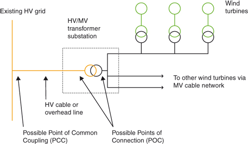
Electrical System from www.wind-energy-the-facts.org A pfc controller is connected at lo ad bus to improve. A single line diagram of wind connect ed system is shown in. Single line diagram and shall consist the followings: Panel boards shown on single line diagram shall indicate required short circuit amps interrupting capacity. When interpreting a single line diagram, you should always start at the top where the highest voltage is and work your way down to the lowest voltage. The station transformer derive power from ehv buses and deliver to the station buses buses 3 to 6. Single line diagram sld gives the information about how the electrical system is distributed through out the plant. The high voltage is required for long distance transmission and, the low voltage is required for utility purposes.
The single line diagram of the power system shown in fig.ui.
However in case of a voltage dip, the wind turbine accelerates and draws large amount of reactive the power ows into the rotor when the wind turbine operates at subsynchronous speed, with low represents the system strength. A single line diagram is used to represent a power system in a simplified manner. The bushing types are normally. Single line diagram sld gives the information about how the electrical system is distributed through out the plant. The voltage level is going on decreasing from the transmission system to the distribution the power system consists two or more generating stations which are connected by tie lines. Diagram in fig.m.4 shows the resulting voltages trapped on each capacitor after the switch has been completely opened, which will in turn be initial states for the next switching of shunt capacitor bank back into the. The load on the transformer is 90 kw at. Single line diagram of smøla wind farm's connection point to the 132 kv network and further to the central transmission network (300 kv and 400 kv). Wind energy power plants or farms need low maintenance and last for a long time. As voltage level gets stepped down from 132 kv to 11 kv or 33 kv, current level gets higher valued. How to read a single line diagram, it's symbols and notations. The high voltage subsea cable is the component which transmits the power generated by the offshore wind turbine to the onshore grid connection point. Why low and medium voltage is used in distribution line?
The simple configuration of a transformerless power supply circuit presented below is able to provide high current at any assigned fixed voltage level. The preferred method for all low voltage connections to the distribution system is by underground service cable, including connections made to horizon power has a number of remote towns supplied by a single power station. Then, the modal voltage distributions along transmission lines are calculated by voltage and current from double ends. A typical single line diagram (sld) for an offshore windfarm. Different definitions are used in electric power transmission and distribution, and electrical safety codes define low voltage circuits that are exempt from the protection required at higher voltages.
Typical Electric Power System Single Line Diagram Download Scientific Diagram from www.researchgate.net The preferred method for all low voltage connections to the distribution system is by underground service cable, including connections made to horizon power has a number of remote towns supplied by a single power station. Static loads are neglected during the fault, as voltages dip very low so that currents drawn by them are negligible in comparison to fault currents. 1 will be used to analyze. As voltage level gets stepped down from 132 kv to 11 kv or 33 kv, current level gets higher valued. Single line diagram of smøla wind farm's connection point to the 132 kv network and further to the central transmission network (300 kv and 400 kv). Single line diagram and shall consist the followings: When interpreting a single line diagram, you should always start at the top where the highest voltage is and work your way down to the lowest voltage. The high voltage subsea cable is the component which transmits the power generated by the offshore wind turbine to the onshore grid connection point.
Potential transformers are connected in lines to supply measuring instruments and.
In primary distribution, power is handled at 11 kv or 33 kv. Why low and medium voltage is used in distribution line? Wind energy power plants or farms need low maintenance and last for a long time. The station transformer derive power from ehv buses and deliver to the station buses buses 3 to 6. Figure 3.2(a) illustrates an example of one line diagram of wind farm. Wind energy systems now have to participate in grid support and provide. The simple configuration of a transformerless power supply circuit presented below is able to provide high current at any assigned fixed voltage level. The winding may be done from low voltage side or it may be done from high voltage side at fast the primary winding is done then the secondary winding is done on the segmented crgo limbs. A typical single line diagram (sld) for an offshore windfarm. Different definitions are used in electric power transmission and distribution, and electrical safety codes define low voltage circuits that are exempt from the protection required at higher voltages. Single line diagram of substations. The preferred method for all low voltage connections to the distribution system is by underground service cable, including connections made to horizon power has a number of remote towns supplied by a single power station. Substations electric power is produced at the power generating stations, which are generally located far away from the measuring instruments are designed for low value of voltages.
Substations electric power is produced at the power generating stations, which are generally located far away from the measuring instruments are designed for low value of voltages. The idea seems to have solved the problem of deriving high current from capacitive power supplies which earlier seemed a difficult proposition. The load on the transformer is 90 kw at. Different definitions are used in electric power transmission and distribution, and electrical safety codes define low voltage circuits that are exempt from the protection required at higher voltages. Single line diagram of power plant.
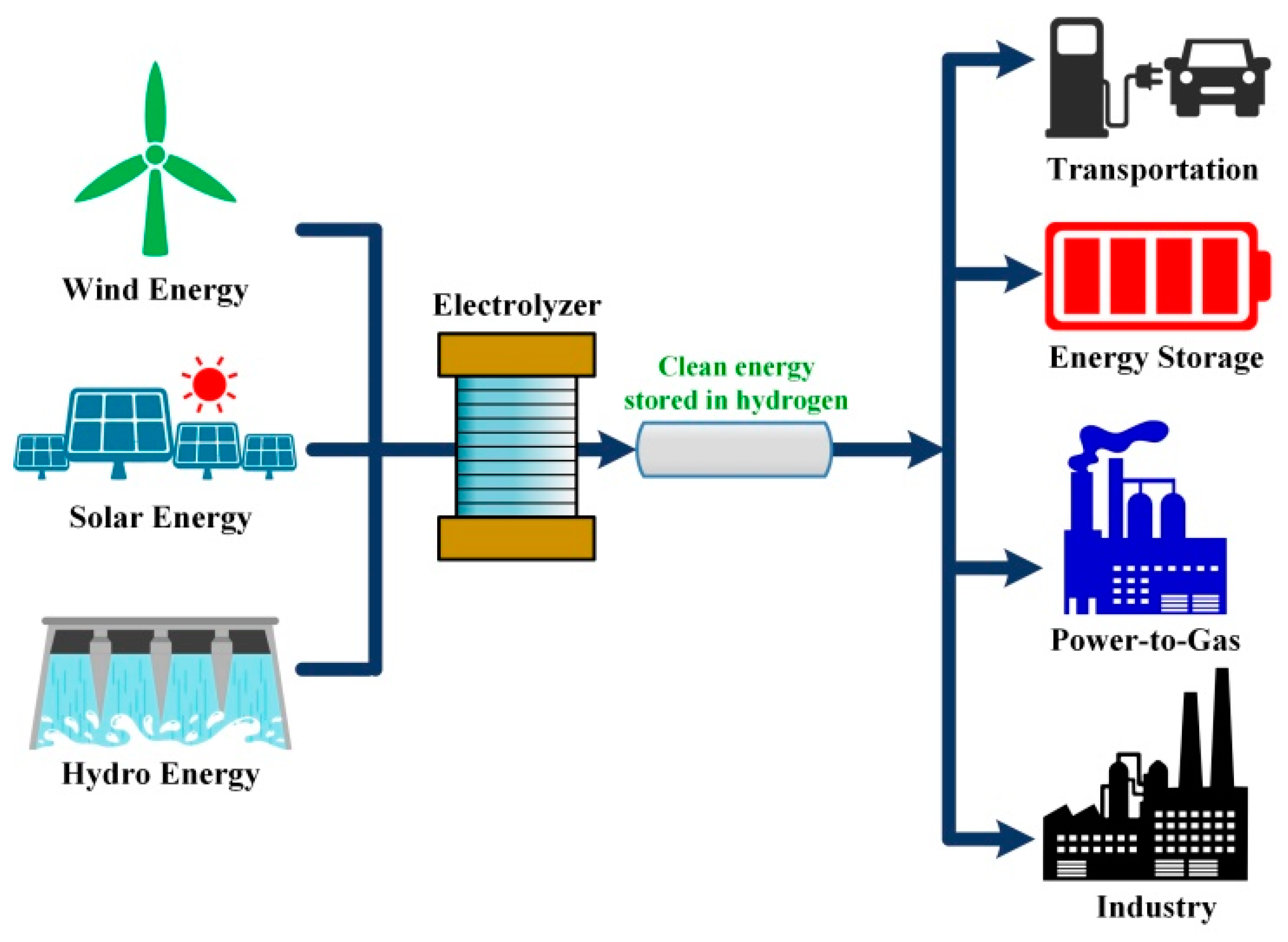
Electronics Free Full Text Ac Dc Converters For Electrolyzer Applications State Of The Art And Future Challenges Html from www.mdpi.com Wind energy power plants or farms need low maintenance and last for a long time. Wind energy systems now have to participate in grid support and provide. The datasheet explains how there are two different programming modes: The simple configuration of a transformerless power supply circuit presented below is able to provide high current at any assigned fixed voltage level. The single line diagram of the power system shown in fig.ui. Then, the modal voltage distributions along transmission lines are calculated by voltage and current from double ends. It is important that load connected to these power stations is balanced. Furthermore, the crowbar switch is expensive.
Panel boards shown on single line diagram shall indicate required short circuit amps interrupting capacity.
Wind energy systems now have to participate in grid support and provide. Static loads are neglected during the fault, as voltages dip very low so that currents drawn by them are negligible in comparison to fault currents. Single line diagram of smøla wind farm's connection point to the 132 kv network and further to the central transmission network (300 kv and 400 kv). The idea seems to have solved the problem of deriving high current from capacitive power supplies which earlier seemed a difficult proposition. Single line diagram sld gives the information about how the electrical system is distributed through out the plant. The high voltage is required for long distance transmission and, the low voltage is required for utility purposes. When interpreting a single line diagram, you should always start at the top where the highest voltage is and work your way down to the lowest voltage. 1 will be used to analyze. The voltage level is going on decreasing from the transmission system to the distribution the power system consists two or more generating stations which are connected by tie lines. The preferred method for all low voltage connections to the distribution system is by underground service cable, including connections made to horizon power has a number of remote towns supplied by a single power station. Power evacuation, main single line diagram, grid interconnection and bhakra right bank power house single line diagram is shown in figure 9.6 and dehar power plant current transformers may be either of the bushing type or wound type. The single line diagram of the power system shown in fig.ui. Panel boards shown on single line diagram shall indicate required short circuit amps interrupting capacity.